The plastic tube was a part of a car, precisely an old Fiat Panda...
Else known as Small Transmitting Loop or STL, this isn't a traditional "electric" antenna, because the "near field" is almost "magnetic". This interesting feature makes the ground plane losses very low and generally this antenna has little dimensions. Besides, STL produces little or no TVI and reception is clear from static noises and man made noises, this has a very narrow bandwidth (50 KHz) and for this reason is little or nothing disturbed from near strong signals (splatters).
If you look for commercial "loops" on the Internet, you'll find "monster" prices for them and if you aren't a Rockefeller, you'll never buy one of this smart antennas.
In 2004, I built a couple of them, a little one of 40 cm diameter and another one of 73 cm for 27 MHz but this last antenna runs from 23 MHz to 36 MHz with the capacitor I've made.
Do you like to build something with your
hands?
If so, this is the right place. I'm not a Radio Amateur, I'm
simply a radio user, maybe a radio lover, so if I'm able to make
this antenna to run, why not you?
NOTE: All my antennas are built by recovered parts, so as to restore to life parts that will end to dump and be sure you'll not spend an arm and a leg!
Below, I describe my antenna, but you can modify near all the parameters with a lot of nice programs that you'll can find @ the links at the end of this page.
Recipe:
I recovered the copper tube in an industrial dump store for 1 €, it had a very bad shape, not linear, nor circular, so I had to straighten the tube before I could use it.
| Then I built a perfect circle in a very easy way: I taken a wheel rim of a sport bike, then pressed the tube against the rim's throat and MIRACLE! A perfect circle was done in about 20 seconds, am I like Giotto? :-) | |
|
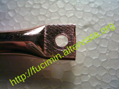
Next I pressed the end of the tube in a vice and drilled a hole for end. |
| Now prepare the holes to pass the
copper tube through... The plastic tube was a part of a car, precisely an old Fiat Panda... |
ehm... what is look like this? Click on the
photo ;-) |
|
So far, the job was easy to do. The most important and hardest thing to build of this antenna is the Butterfly capacitor. A good build is needed, else antenna's efficiency will be very low. |
Notice that even at low power (5 Watts), there is a High RF Voltage ranging from 800 to 1600 Volt.
So, don't touch the capacitor when transmitting!
 Danger of death!
The capacitor I built supports easily 5 Watts but I think I could use it up to 300-500 Watts, nevertheless I never tried power greater than 12 Watts (SSB).
This is all you need to build a
Butterfly capacitor:
|
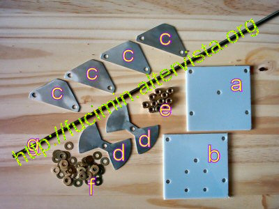 |
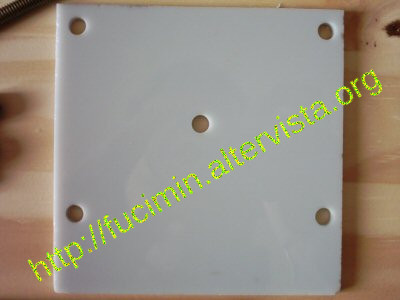
"a and "b" are the insulators and support the capacitor's stators and rotor.
The hardest part is to cut "c" and "d", because the scissors tend to deform and roll up aluminium so, at the end, you'll need to straighten the plates and you'll have to be VERY precise and to file a lot! Don't be in a hurry: do a good job!
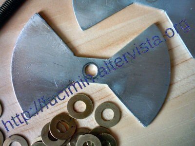 |
This is an aluminium "butterfly" ready to be installed. |
| ...and here an aluminium plate for the stator. | 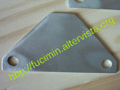 |
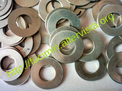 |
brass washers... |
| brass bolts | 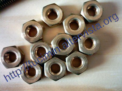 |
 |
Be precise!!! |
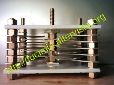
| Butterfly Capacitor mounted on the loop. | 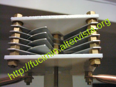 |
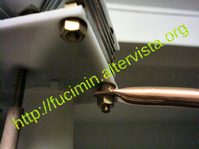 |
another shot of the Butterfly capacitor-Loop... |
| Here is the coupling loop. The coupling loop diameter is 1/5 of loop diameter and the easy way to build is using a piece of a copper wire, some use RG58 but it's a little bit difficult. |  |
 |
A photo of motor and gear for tuning the capacitor. The next photo shows the particular of gear, ALL made from recovered parts of broken printers, both the stepper motor and mechanisms. The whole thing, gears down exaggerately with a 96:1 (96 stepper motor's turns for a 1 butterfly's rotor turn) that means 18432 step/revolution, very precise movement! :) |
| The gear... | 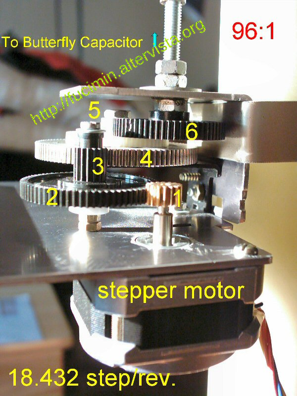 |
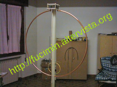 |
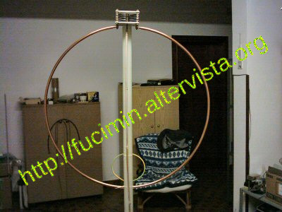
The Small Transmitting Loop completed. This antenna was tested only indoor on the ground floor. Maximum distance reached was 55 km in central band, AM. This antenna has a deep null, very useful when present unwanted signals near the wanted one. VSWR is 1:1 but needs to be corrected when you move up or down 3-4 channels. |
|
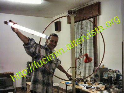
Here some nice experiments: when transmitting, you can
light up a neon tube without plug it to the current! With
light on and...
...then with light off... |
 |
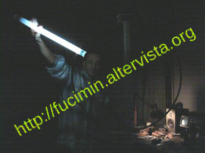 |
What do you think, isn't there a little resemblance with
Uncle Fester? ;-)
|
| Below, you can "see" the electromagnetic field, approaching a neon tube! |  |
 |
Here is what you have to prepare to build the capacitor. Many pieces... |
| Magnetic Loop Design Software | |
|---|---|
| LoopCalc | Runs under Windows |
| MagLoop4 | Runs under DOS-Windows |
| RJELOOP1 | Runs under DOS-Windows |